Difference between revisions of "Use usbserial adapter"
From Yantrr Wiki
| Line 3: | Line 3: | ||
* For ssh and console access to VIBE2 over UART port, use a 3.3V UART to USB adapter. | * For ssh and console access to VIBE2 over UART port, use a 3.3V UART to USB adapter. | ||
| + | |||
[[File:VIBE2_jumper1.jpg|400px]] | [[File:VIBE2_jumper1.jpg|400px]] | ||
| + | |||
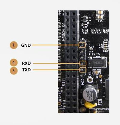
* On VIBE2 there are two UART0 headers provided J1 (33) and P7(25). | * On VIBE2 there are two UART0 headers provided J1 (33) and P7(25). | ||
* Each VIBE2 is provided with a USB-to-UART adapter and a 3 wire jumper cable. It has to be interfaced with VIBE2 in the following manner : | * Each VIBE2 is provided with a USB-to-UART adapter and a 3 wire jumper cable. It has to be interfaced with VIBE2 in the following manner : | ||
| − | a. GND pin on adapter : Pin J1.1 (GND) | + | a. GND pin on adapter : Pin J1.1 (GND) |
| − | b. TX pin on adapter : Pin J1.4 (RXD) | + | b. TX pin on adapter : Pin J1.4 (RXD) |
| − | c. RX Pin on adapter : Pin J1.5 (TXD) | + | c. RX Pin on adapter : Pin J1.5 (TXD) |
* Similar interface can be done with P7 UART0 header if J1 is inaccessible when a cape is mounted. P7 header has markings on the board. | * Similar interface can be done with P7 UART0 header if J1 is inaccessible when a cape is mounted. P7 header has markings on the board. | ||
| Line 21: | Line 23: | ||
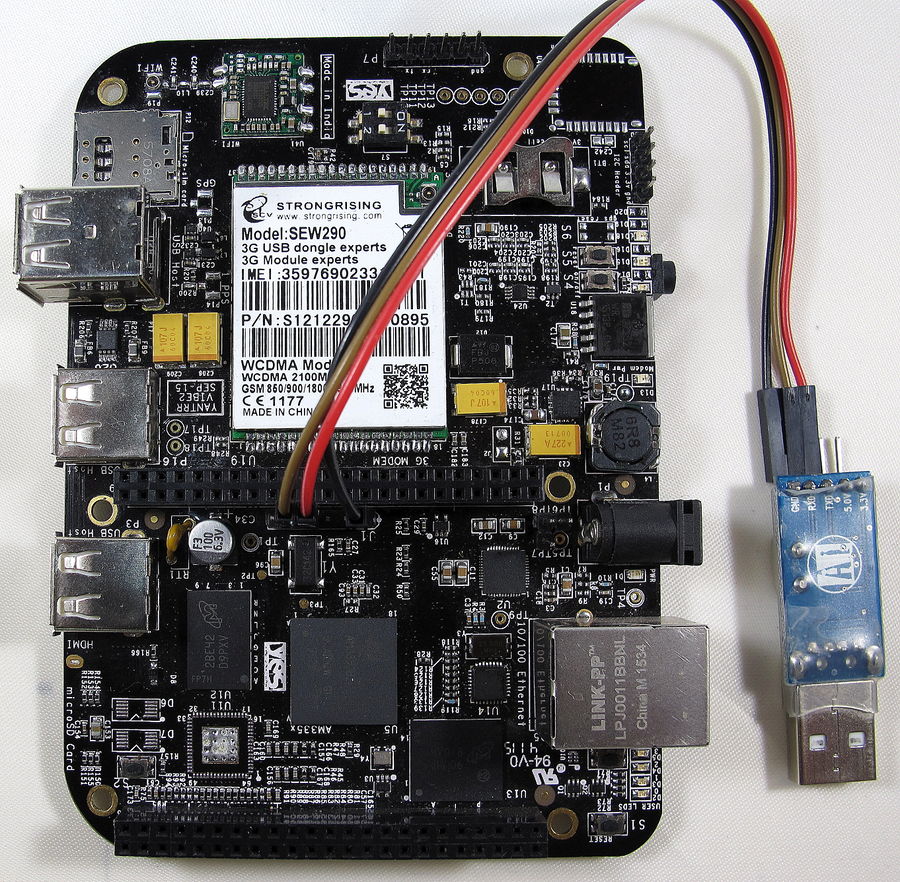
Please refer to the image provided below for connections. | Please refer to the image provided below for connections. | ||
| + | |||
[[File:IMG_22411.JPG|900px]] | [[File:IMG_22411.JPG|900px]] | ||
Revision as of 04:55, 12 July 2016
VIBE2 also provides a USB-UART serial connectivity for ssh.
INSTRUCTIONS
- For ssh and console access to VIBE2 over UART port, use a 3.3V UART to USB adapter.
- On VIBE2 there are two UART0 headers provided J1 (33) and P7(25).
- Each VIBE2 is provided with a USB-to-UART adapter and a 3 wire jumper cable. It has to be interfaced with VIBE2 in the following manner :
a. GND pin on adapter : Pin J1.1 (GND)
b. TX pin on adapter : Pin J1.4 (RXD)
c. RX Pin on adapter : Pin J1.5 (TXD)
- Similar interface can be done with P7 UART0 header if J1 is inaccessible when a cape is mounted. P7 header has markings on the board.
- Connect the USB port of the adapter to a Host (like a PC).
- Open the serial/COM port on the Host in a serial port emulator like Putty with following parameters :
Baud rate : 115200, 8 data bits, No parity bit and 1 stop bit
- For windows, check Device manager for COM port against PL2303 USB devices.
- In Linux, simple interface like /dev/ttyUSB0 should be available.
Please refer to the image provided below for connections.

