Difference between revisions of "VIBEQ"
From Yantrr Wiki
(→LEDs) |
(→LEDs) |
||
| Line 35: | Line 35: | ||
{| class="wikitable" style="margin: auto;" | {| class="wikitable" style="margin: auto;" | ||
|- | |- | ||
| − | ! LED !! Description | + | ! style="text-align: center; background-color:#cbcefb;" | LED !! style="text-align: center; background-color:#cbcefb;" | Description |
|- | |- | ||
| − | | D1 || Power LED | + | | style="text-align: center;"| D1 || Power LED |
|- | |- | ||
| − | | D2 || User LED 0 | + | | style="text-align: center;"| D2 || User LED 0 |
|- | |- | ||
| − | | D3 || User LED 1 | + | | style="text-align: center;"| D3 || User LED 1 |
|- | |- | ||
| − | | D4 || User LED 2 | + | | style="text-align: center;"| D4 || User LED 2 |
|- | |- | ||
| − | | D5 || User LED 3 | + | | style="text-align: center;"| D5 || User LED 3 |
|- | |- | ||
| − | | D13 || Modem Power LED | + | | style="text-align: center;"| D13 || Modem Power LED |
|- | |- | ||
| − | | D14 || Modem operation status LED | + | | style="text-align: center;"| D14 || Modem operation status LED |
|- | |- | ||
| − | | D15 || Modem network activity status LED | + | | style="text-align: center;"| D15 || Modem network activity status LED |
|- | |- | ||
| − | | D16 || Modem network registration mode LED | + | | style="text-align: center;"| D16 || Modem network registration mode LED |
|- | |- | ||
| − | | D18 || Cape Side Power LED | + | | style="text-align: center;"| D18 || Cape Side Power LED |
|- | |- | ||
| − | | D20 || Diagnostic status LED | + | | style="text-align: center;"| D20 || Diagnostic status LED |
|} | |} | ||
Revision as of 06:34, 14 May 2018
Contents
[hide]Overview
Quick Start Guide
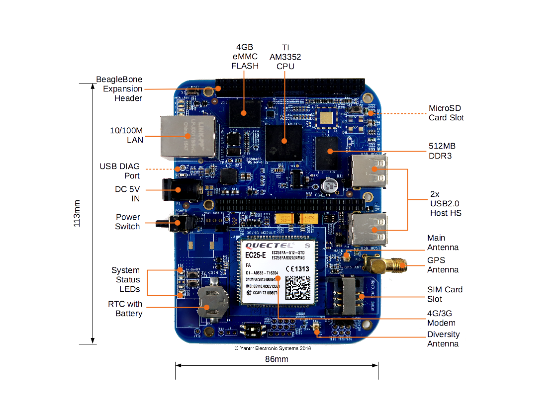
Board Layout
Jumpers
| Jumper | Description |
|---|---|
| J2 | Battery connection bypass jumper, for non BATT-UPG configurations this jumper should be closed. |
| J3 | Boost section bypass jumper, for non BATT-UPG configurations this jumper should be closed. |
Switches
| Switch | Description |
|---|---|
| S1 | Reset switch |
| S2 | Boot switch |
| S3 | Power switch |
| S4 | Modem ON/OFF switch |
| S5 | Modem Reset switch |
| S7 | Cape address switch |
LEDs
| LED | Description |
|---|---|
| D1 | Power LED |
| D2 | User LED 0 |
| D3 | User LED 1 |
| D4 | User LED 2 |
| D5 | User LED 3 |
| D13 | Modem Power LED |
| D14 | Modem operation status LED |
| D15 | Modem network activity status LED |
| D16 | Modem network registration mode LED |
| D18 | Cape Side Power LED |
| D20 | Diagnostic status LED |
