Difference between revisions of "VIBEQ"
(→Precompiled Images) |
(→Quick Start Guide) |
||
| Line 28: | Line 28: | ||
| [[File:vibeq-ledsTable.png|VIBEQ LEDs | auto]] | | [[File:vibeq-ledsTable.png|VIBEQ LEDs | auto]] | ||
|} | |} | ||
| + | |||
| + | ===Headers Pinout Details=== | ||
| + | [[File:VIBEQ-Header-Pinout.png|VIBEQ Header Pinout | center]] | ||
=Getting Started= | =Getting Started= | ||
Revision as of 07:01, 4 April 2019
Contents
[hide]Overview
VIBEQ is an IoT hardware platform which provides a unique combination of industrial sensor interfaces like SPI, I2C, RS232, CAN, GPIO, PWM, ADC, HDMI, a worldwide 3G/4G/LTE connectivity option and a low power ARM processor for both industrial machine-to-machine (M2M) and home IoT applications. VIBEQ is a dedicated IoT platform which provides connectivity and processing power in a easy to deploy 2x credit card size form-factor.
The VIBEQ platform has been redesigned to improve and extend the original BeagleBone platform while remaining fully compatible in both hardware and software aspects.
- Redesigned Ethernet PHY power up reset circuits to ensure reliable trouble free operation in every power cycle
- Watch dog timer to ensure fail-safe operation of CPU's power management circuit
- Reconfigured USB port extended to powered hub to eliminate USB device power down issues
- Standard high precision battery backed RTC (Real Time Clock)
- New 4G/LTE support for all regions of the world, 3G/HSPA worlwide bands option is also available
- Integrated GNSS receiver
Quick Start Guide
VIBEQ - RevA Quick Start Guide [PDF]
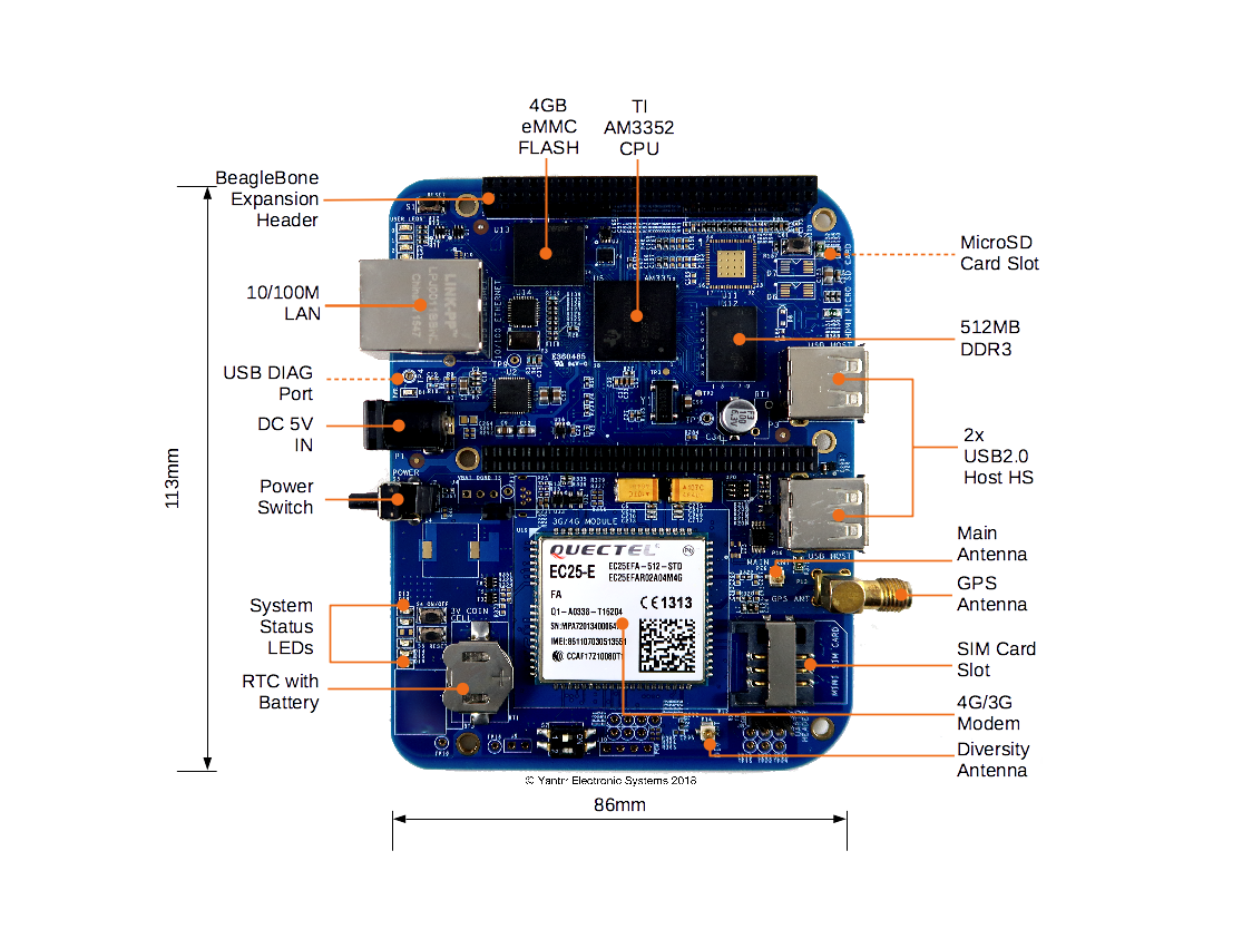
Board Layout
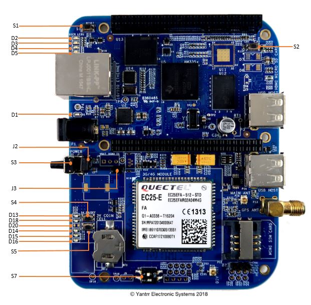
Jumpers, Switches, LEDs

|
|
|
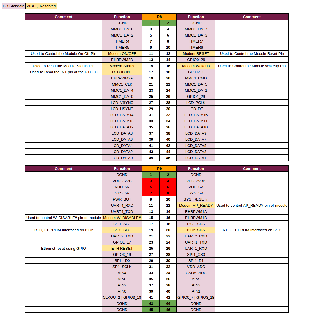
Headers Pinout Details
Getting Started
Setting up the system
- Place 3V coin cell(supplied with VIBEQ) in the holder for RTC.
- Place a data enabled mini-SIM in the SIM card slot and connect a GSM antenna to the respective main antenna connector using uFL connectors.
- Ensure that the power jumpers J2 and J3 on VIBEQ are in place and eeprom address set at 0x54 using dip switch S7
- Power up VIBEQ using the 5V,5A DC adapter (supplied with VIBEQ).
|
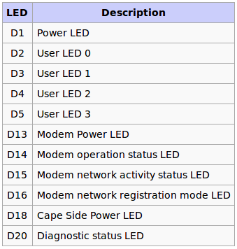
Before proceeding further ensure D1 LED is glowing properly. Make sure that the adapter being used is of proper rating and has been connected properly. |
|
Before powering down the system always ensure to Turn OFF the Modem using the PWRKEY turn ON/OFF control pin or using the AT Command AT+QPOWD. |
Accessing the System
Through Mini-USB Diagnostic Port
The diagnostic port (P4 at the back side of USER LEDs) will gives debug-console access to VIBEQ. Connect a Mini-USB cable between VIBEQ’s diagnostic port and Desktop USB port. Once connected to Desktop system two virtual ports are created on the desktop. Depending on Desktop OS, ports name will be different.
On Linux :
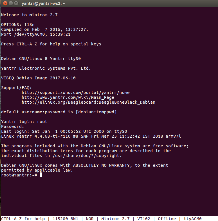
It will create port /dev/ttyACM0 and /dev/ttyACM1. Use minicom or similar application for accessing serial port /dev/ttyACM0 with default baud rate of 115200
sudo minicom -D /dev/ttyACM0
On Windows :
First check the serial port names using Windows Device Manager Utility.
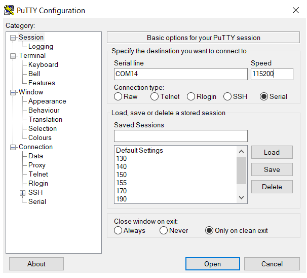
Here, Diagnostic Port of VIBEQ is accessible on port COM14, now use putty client to access it.
Through Ethernet
|
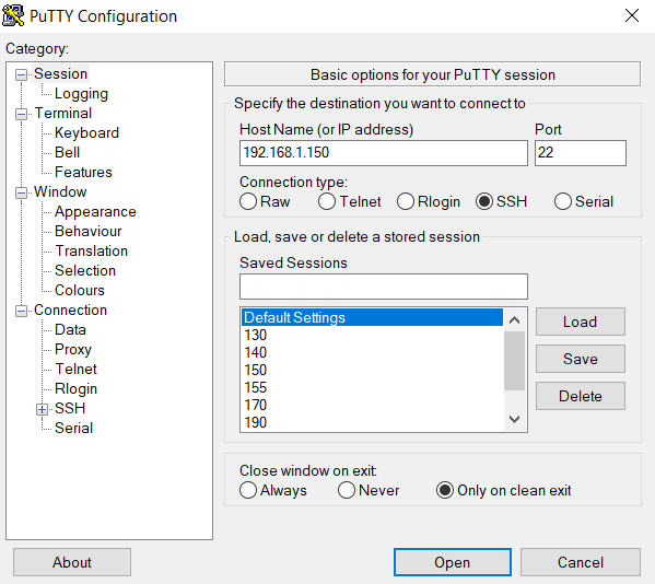
In Yantrr Pre-compiled images, the Ethernet IP address is set to static IP 192.168.1.150. If you are using DHCP IP then Ethernet IP be should be know and the same should be used while making ssh connection. |
On Linux :
ssh root@192.168.1.150
On Windows : (Using Putty Client)
|
Username for root login is root and password is root. |
Modem Ports
VIBEQ has an option between 3G/HSPA+ and 4G/LTE,CAT4 modem for WAN connectivity.
- 3G Modem : VIBEQ-3GUC20-x comes with Quectel UC20 3G modem.
- 4G Modem : VIBEQ-4GEC25-x comes with Quectel EC25 4G modem.
Both 3G/4G modem creates 5 ports :
- /dev/ttyUSB0 : DM
- /dev/ttyUSB1 : For GPS NMEA message output
- /dev/ttyUSB2 : For AT commands
- /dev/ttyUSB3 : For PPP connections or AT commands
- /dev/cdc-wdm0 : QMI WWAN Port
Modem Control
Please ensure that the modem is properly turned on before ppp connections can be established. If PPP connection cannot be established properly, soft reset the modem following the timing procedures for modem.
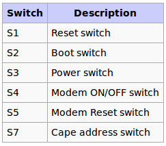
The modem can be powered on/off by either using the push button switch S4 or GPIO45.
Power on
The module will be turned off after power-on(when power is supplied) normally. In the state of power off, provide a high level pulse atleast for 100 Milliseconds to ON/OFF PIN to turn on the module by either toggling the push button switch or by cycling the GPIO through Low-High cycle.
The default state of ON/OFF GPIO should be low.
cd /sys/class/gpio
echo 45 > export
cd gpio45
echo “low” > direction
cd /sys/class/gpio/gpio45
echo "high" > direction
sleep 0.1
echo "low" > direction
|
In Yantrr Pre-Compiled VIBEQ Boot Image, all modem related GPIOs are set for its desired usage, hence the modem will get powered ON on its boot up. |
Check that modem is visible on the USB bus by :
root@Yantrr:~# lsusb
Bus 002 Device 002: ID 2c7c:0125
Bus 002 Device 001: ID 1d6b:0002 Linux Foundation 2.0 root hub
Bus 001 Device 002: ID 0424:2412 Standard Microsystems Corp.
Bus 001 Device 001: ID 1d6b:0002 Linux Foundation 2.0 root hub
|
In Yantrr Pre-Compiled VIBEQ Boot Image, for ease of user these regular commands with the GPIOs have been created as functions : pinexp, setout, setin, pinread. |
pinexp 45
pinexp 44
setout 45 low
setout 44 high
Power off
In the state of Power On, provide atleast a 700 Milliseconds low level pulse to ON/OFF PIN to turn off the module.
cd /sys/class/gpio/gpio45
echo "high" > direction
sleep 0.7
echo "low" > direction
Soft Reset
To soft reset the modem, cycle the Modem On/Off pin through a Power-Off and then Power-On cycle. i.e.
- Power Off the Modem.
- Wait for 1-2s atleast.
- Power on the modem.
Hard Reset
There might arise situations where modem does not seem to be responding to any commands issued on AT commands port or it cannot be turned on/off. In such scenarios, issue hard reset to the modem. It can be done by either toggling Switch S5 for atleast 500ms or pulling GPIO44 low for 1s and then setting it high again.
cd /sys/class/gpio/
cd gpio44
echo "low" > direction
sleep 0.5
echo "high" > direction
|
Please use hard reset conservatively. Soft reset should be preferred under most conditions. |
PPP connection using wvdial
Download and install Wvdial
apt-get install wvdial
Open the wvdial.conf file
$ nano /etc/wvdial.conf
Assuming that you have the USERNAME, PASSWORD and APN available for the service provider of the sim card being used, edit and make wvdial.conf file like this. Sample wvdial.conf file for AT&T and T-Mobile USA
[Dialer Defaults]
Modem Type = Analog
ModemPhone = *99#
ISDN = 0
Baud = 115200
Username = USERNAME
Password = PASSWORD
Modem = /dev/ttyUSB3
Init1 = ATZ
Init2 = ATQ0 V1 E1 S0=0 &C1 &D2 +FCLASS=0
Init3 = at+cgdcont=1,"ip","APN"
Stupid Mode = 1
Usually for GSM Networks, Modemphone is *99# or *99***1#. Consult your network provider for exact details in case you are facing difficulties. After editing, save and exit, now run wvdial for establishing communication.
$ wvdial
If all parameters are correct and everything is working, you should see a success message from wvdial. Once PPP connection has been established, you will see a ppp0 IP.
To check the status of wvdial and find out its IP open a new shell and use either of following:
- Run ifconfig and find ppp0 in the list of network connections.
$ ifconfig
or
$ ifconfig ppp0
- Check the network statistics for IP and their gateways and check the Iface column for ppp0
$ netstat -arn
* Kernel IP routing table

Destination Gateway Genmask Flags MSS Window irtt Iface
0.0.0.0 192.168.1.1 0.0.0.0 UG 0 0 0 eth0
192.168.1.0 0.0.0.0 255.255.255.0 U 0 0 0 eth0
192.168.7.0 0.0.0.0 255.255.255.252 U 0 0 0 usb0
192.200.1.21 0.0.0.0 255.255.255.255 UH 0 0 0 ppp0
- Read the system messages as
$ cat /var/log/messages
It lists all the attempts at establishing ppp communication using the modem and IPs for the successful attempt.
Now all that is left is to route the network traffic over the gateway of ppp0 instead of eth0 so that GPRS communication is fully completed.
GPS
UC20/EC25 GNSS engine allows calculating location without any assistance from the network.
|
Please note that the /dev/ttyUSB1 is only GPS NMEA message output port |
- Turn ON GNSS
AT+QGPS=1
Note : By default GNSS engine is in OFF state on Modem Power Up.
- Turn OFF GNSS
AT+QGPSEND
- Positioning Information
AT+QGPSLOC?
For more AT commands refer device specific manuals from below section.
AT Commands Manual
All the AT commands can be executed on the serial port /dev/ttyUSB2 with baud rate of 115200 8N1.
- 3G Modem (UC20)
- 4G Modem (EC25)
RTC
VIBEQ has an accurate Real Time clock with an integrated temperature compensated oscillator and crystal for time keeping operations.
- It includes a 3V non-chargeable coin cell ( CR1025/CR1216/CR1220) for standby power.
- RTC (DS3231) is interfaced over I2C2 to AM3352 processor.
- RTC IC generates a 1Hz Square wave signal. This signal is available on GPIO27 (Optional).
Setting up RTC
The RTC uses I2C2 and all the transfers are made through it. So, we can verify its presence by using the command
i2cdetect -y -r 1
An ID 68 can be seen on the address 0x68 which shows the presence of RTC. This means that the module is wired up and is verified
Now, to set up the DS3231 RTC module use command
echo ds1307 0x68 > /sys/class/i2c-adapter/i2c-1/new_device
To read the present time from RTC module, use command
hwclock -r -f /dev/rtc1
To write the current system time on RTC module, use command
hwclock -w -f /dev/rtc1
To update the system time using the RTC module, use command
hwclock -s -f /dev/rtc1
|
In pre-compiled Debian Yantrr Image, RTC module is set and configured to update the system time from it on boot up using boot_run.sh script. Only, after very first boot up of VIBEQ, user need to update correct time on RTC module. |
Software Setup Guide
For use of VIBEQ, we recommend to use pre-compiled Debian Yantrr Image. The pre-compiled Debian Yantrr Image has all the settings pre-configured for use of its various features such as 3G/4G modem, GPS, USB Host Ports, RTC, etc.
Precompiled Images
- Debian
- MicroSD card Image :
Also in the Debian Yantrr Image, for configuring various modules of VIBEQ at every boot up a boot_run.sh script is executed. Its content is
root@Yantrr:~# cat boot_run.sh
#!/bin/sh -e
/bin/sleep 10
/bin/echo ==============================
/bin/echo 'Setting pins'
/root/bin/pinexp 117			# Ethernet reset using GPIO
/root/bin/pinexp 44			# Modem RESET Pin
/root/bin/setout 44 high
/root/bin/pinexp 45			# Modem ON/OFF Pin
/root/bin/setout 45 low
/bin/sleep 4
/root/bin/setout 45 high		# Modem Power ON cycle for Quectel UC20 and EC25
/bin/sleep 0.1
/root/bin/setout 45 low
/bin/echo 'Done with pins and devices'
/bin/echo 'Updating RTC time'
/bin/echo ds3231 0x68 > /sys/class/i2c-adapter/i2c-2/new_device		# Setting up RTC on I2C2
# Write RTC time to system
/sbin/hwclock -s -f /dev/rtc1						# Update Hardware RTC1 time to System Time
/sbin/hwclock -w							# Update System time to Hardware Time
/bin/echo 'All done'
|
With pre-compiled Debian Yantrr Image, no need of manual execution of above boot_run.sh. The script is configured to auto execute on board boot up using cronjob entry. |
