Difference between revisions of "Battery backup"
From Yantrr Wiki
| Line 2: | Line 2: | ||
=='''INSTRUCTIONS'''== | =='''INSTRUCTIONS'''== | ||
| + | |||
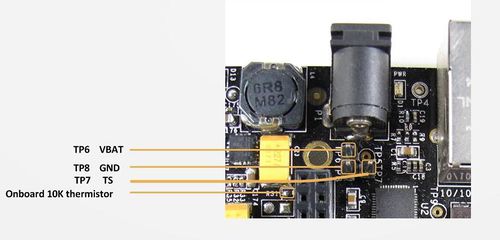
A 2-pin Connector interface is provided at battery test points TP6 and TP8, with a 10K thermistor R31 mounted on PCB to simulate the thermistor circuit for battery charging. | A 2-pin Connector interface is provided at battery test points TP6 and TP8, with a 10K thermistor R31 mounted on PCB to simulate the thermistor circuit for battery charging. | ||
| + | |||
Following is a diagram explaining the battery interfaces on VIBE2 : | Following is a diagram explaining the battery interfaces on VIBE2 : | ||
| + | |||
| + | |||
[[File:VIBE2_battery.jpg|500px]] | [[File:VIBE2_battery.jpg|500px]] | ||
| + | |||
Follow the given steps to change the battery charging conditions : | Follow the given steps to change the battery charging conditions : | ||
* Connect a 3.7V Li-Po battery of sufficient capacity with its VBAT to TP6 and GND to TP8. | * Connect a 3.7V Li-Po battery of sufficient capacity with its VBAT to TP6 and GND to TP8. | ||
| + | |||
| + | |||
* Issue the following commands in console : | * Issue the following commands in console : | ||
| + | |||
a) Change battery charging range to 0-60 degree C | a) Change battery charging range to 0-60 degree C | ||
# i2cset -f -y 0 0X24 6 0Xb3 b | # i2cset -f -y 0 0X24 6 0Xb3 b | ||
| + | |||
b) Change battery charging voltage to 4.2V | b) Change battery charging voltage to 4.2V | ||
# i2cset -f -y 0 0X24 5 0Xa0 b | # i2cset -f -y 0 0X24 5 0Xa0 b | ||
| + | |||
'''NOTE:''' When board is powered up only by battery then Power switch S3 has to be pressed to turn it on. | '''NOTE:''' When board is powered up only by battery then Power switch S3 has to be pressed to turn it on. | ||
| + | |||
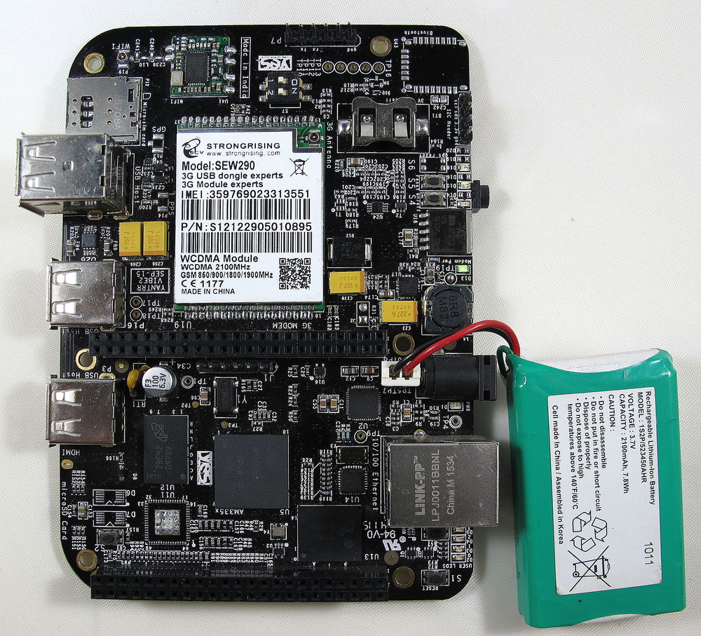
Please refer to image provided below for battery connections | Please refer to image provided below for battery connections | ||
| − | [[File:IMG_22381. | + | |
| + | [[File:IMG_22381.JPG|1000px]] | ||
Revision as of 05:03, 12 July 2016
VIBE2 provides an optional battery circuit for standby purposes.
INSTRUCTIONS
A 2-pin Connector interface is provided at battery test points TP6 and TP8, with a 10K thermistor R31 mounted on PCB to simulate the thermistor circuit for battery charging.
Following is a diagram explaining the battery interfaces on VIBE2 :
Follow the given steps to change the battery charging conditions :
- Connect a 3.7V Li-Po battery of sufficient capacity with its VBAT to TP6 and GND to TP8.
- Issue the following commands in console :
a) Change battery charging range to 0-60 degree C
# i2cset -f -y 0 0X24 6 0Xb3 b
b) Change battery charging voltage to 4.2V
# i2cset -f -y 0 0X24 5 0Xa0 b
NOTE: When board is powered up only by battery then Power switch S3 has to be pressed to turn it on.
Please refer to image provided below for battery connections

