VIBEQ
From Yantrr Wiki
Contents
[hide]Overview
Quick Start Guide
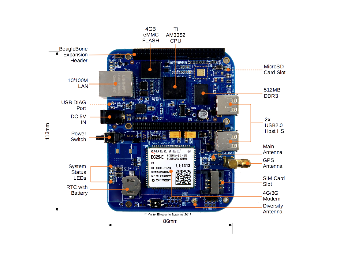
Board Layout
Jumpers
| Jumper | Description |
|---|---|
| J2 | Battery connection bypass jumper, for non BATT-UPG configurations this jumper should be closed. |
| J3 | Boost section bypass jumper, for non BATT-UPG configurations this jumper should be closed. |
Switches
| Switch | Description |
|---|---|
| S1 | Reset switch |
| S2 | Boot switch |
| S3 | Power switch |
| S4 | Modem ON/OFF switch |
| S5 | Modem Reset switch |
| S7 | Cape address switch |
LEDs
| LED | Description |
|---|---|
| D1 | Power LED |
| D2 | User LED 0 |
| D3 | User LED 1 |
| D4 | User LED 2 |
| D5 | User LED 3 |
| D13 | Modem Power LED |
| D14 | Modem operation status LED |
| D15 | Modem network activity status LED |
| D16 | Modem network registration mode LED |
| D18 | Cape Side Power LED |
| D20 | Diagnostic status LED |
Getting Started
Setting up the system
- Place 3V coin cell(supplied with VIBEQ) in the holder for RTC.
- Place a data enabled mini-SIM in the SIM card slot and connect a GSM antenna to the respective main antenna connector using uFL connectors.
- Ensure that the power jumpers J2 and J3 on VIBEQ are in place and eeprom address set at 0x54 using dip switch S7
- Power up VIBEQ using the 5V,5A DC adapter (supplied with VIBEQ).
|
Before proceeding further ensure D1 LED is glowing properly. Make sure that the adapter being used is of proper rating and has been connected properly. |
|
Before powering down the system always ensure to Turn OFF the Modem using the PWRKEY turn ON/OFF control pin or using the AT Command AT+QPOWD. |
Accessing the System
Modem Ports
VIBEQ has an option between 3G/HSPA+ and 4G/LTE,CAT4 modem for WAN connectivity.
- 3G Modem : VIBEQ-3GUC20-x comes with Quectel UC20 3G modem.
- 4G Modem : VIBEQ-4GEC25-x comes with Quectel EC25 4G modem.
Both 3G/4G modem creates 5 ports :
- /dev/ttyUSB0 : DM
- /dev/ttyUSB1 : For GPS NMEA message output
- /dev/ttyUSB2 : For AT commands
- /dev/ttyUSB3 : For PPP connections or AT commands
- /dev/cdc-wdm0 : QMI WWAN Port
