VIBEQ
Contents
[hide]Overview
Quick Start Guide
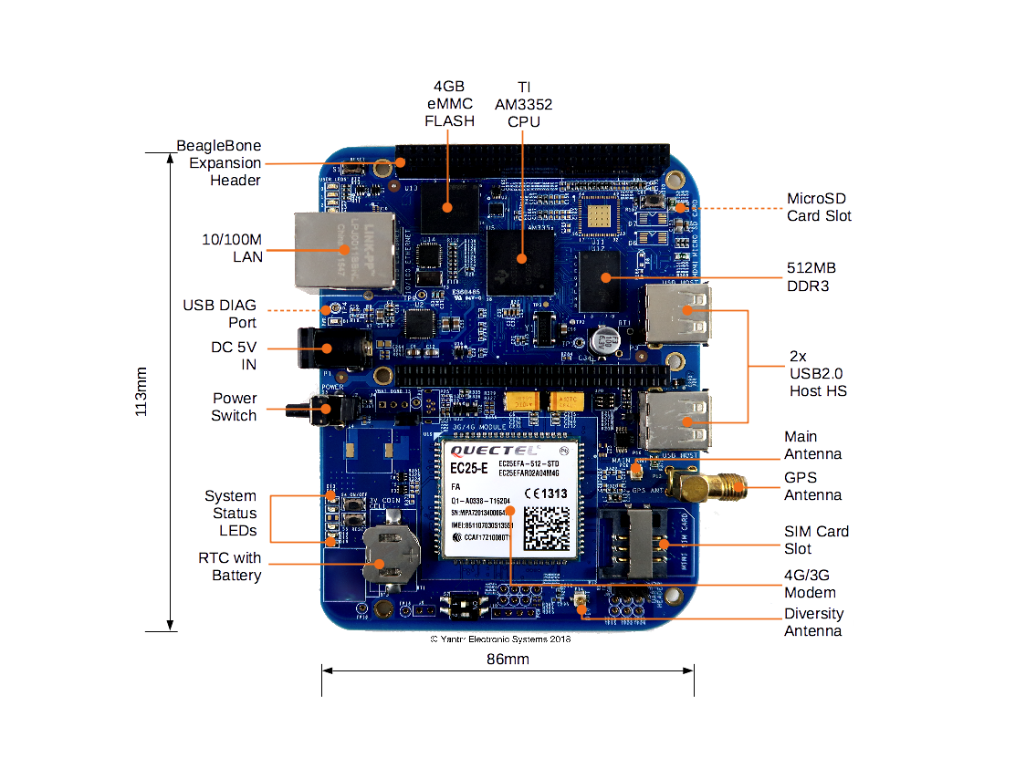
Board Layout
Jumpers
| Jumper | Description |
|---|---|
| J2 | Battery connection bypass jumper, for non BATT-UPG configurations this jumper should be closed. |
| J3 | Boost section bypass jumper, for non BATT-UPG configurations this jumper should be closed. |
Switches
| Switch | Description |
|---|---|
| S1 | Reset switch |
| S2 | Boot switch |
| S3 | Power switch |
| S4 | Modem ON/OFF switch |
| S5 | Modem Reset switch |
| S7 | Cape address switch |
LEDs
| LED | Description |
|---|---|
| D1 | Power LED |
| D2 | User LED 0 |
| D3 | User LED 1 |
| D4 | User LED 2 |
| D5 | User LED 3 |
| D13 | Modem Power LED |
| D14 | Modem operation status LED |
| D15 | Modem network activity status LED |
| D16 | Modem network registration mode LED |
| D18 | Cape Side Power LED |
| D20 | Diagnostic status LED |
Getting Started
Setting up the system
- Place 3V coin cell(supplied with VIBEQ) in the holder for RTC.
- Place a data enabled mini-SIM in the SIM card slot and connect a GSM antenna to the respective main antenna connector using uFL connectors.
- Ensure that the power jumpers J2 and J3 on VIBEQ are in place and eeprom address set at 0x54 using dip switch S7
- Power up VIBEQ using the 5V,5A DC adapter (supplied with VIBEQ).
|
Before proceeding further ensure D1 LED is glowing properly. Make sure that the adapter being used is of proper rating and has been connected properly. |
|
Before powering down the system always ensure to Turn OFF the Modem using the PWRKEY turn ON/OFF control pin or using the AT Command AT+QPOWD. |
Accessing the System
Modem Ports
VIBEQ has an option between 3G/HSPA+ and 4G/LTE,CAT4 modem for WAN connectivity.
- 3G Modem : VIBEQ-3GUC20-x comes with Quectel UC20 3G modem.
- 4G Modem : VIBEQ-4GEC25-x comes with Quectel EC25 4G modem.
Both 3G/4G modem creates 5 ports :
- /dev/ttyUSB0 : DM
- /dev/ttyUSB1 : For GPS NMEA message output
- /dev/ttyUSB2 : For AT commands
- /dev/ttyUSB3 : For PPP connections or AT commands
- /dev/cdc-wdm0 : QMI WWAN Port
Modem Control
Please ensure that the modem is properly turned on before ppp connections can be established. If PPP connection cannot be established properly, soft reset the modem following the timing procedures for modem.
The modem can be powered on/off by either using the push button switch S4 or GPIO45.
Power on
The module will be turned off after power-on(when power is supplied) normally. In the state of power off, provide a high level pulse atleast for 100 Milliseconds to ON/OFF PIN to turn on the module by either toggling the push button switch or by cycling the GPIO through Low-High cycle.
The default state of ON/OFF GPIO should be low.
cd /sys/class/gpio
echo 45 > export
cd gpio45
echo “low” > direction
cd /sys/class/gpio/gpio45
echo "high" > direction
sleep 0.1
echo "low" > direction
|
In Yantrr Pre-Compiled VIBEQ Boot Image, all modem related GPIOs are set for its desired usage, hence the modem will get powered ON on its boot up. |
Check that modem is visible on the USB bus by :
root@Yantrr:~# lsusb
Bus 002 Device 002: ID 2c7c:0125
Bus 002 Device 001: ID 1d6b:0002 Linux Foundation 2.0 root hub
Bus 001 Device 002: ID 0424:2412 Standard Microsystems Corp.
Bus 001 Device 001: ID 1d6b:0002 Linux Foundation 2.0 root hub
|
In Yantrr Pre-Compiled VIBEQ Boot Image, for ease of user these regular commands with the GPIOs have been created as functions : pinexp, setout, setin, pinread. |
pinexp 45
pinexp 44
setout 45 low
setout 44 high
Power off
In the state of Power On, provide atleast a 700 Milliseconds low level pulse to ON/OFF PIN to turn off the module.
cd /sys/class/gpio/gpio45
echo "high" > direction
sleep 0.7
echo "low" > direction
Soft Reset
To soft reset the modem, cycle the Modem On/Off pin through a Power-Off and then Power-On cycle. i.e.
- Power Off the Modem.
- Wait for 1-2s atleast.
- Power on the modem.
Hard Reset
There might arise situations where modem does not seem to be responding to any commands issued on AT commands port or it cannot be turned on/off. In such scenarios, issue hard reset to the modem. It can be done by either toggling Switch S5 for atleast 500ms or pulling GPIO44 low for 1s and then setting it high again.
cd /sys/class/gpio/
cd gpio44
echo "low" > direction
sleep 0.5
echo "high" > direction
|
Please use hard reset conservatively. Soft reset should be preferred under most conditions. |
