Battery backup
From Yantrr Wiki
VIBE2 provides an optional battery circuit for standby purposes.
Instructions
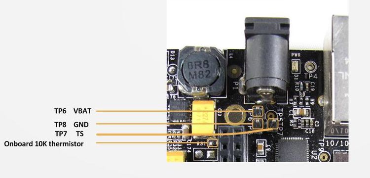
A 2-pin Connector interface is provided at battery test points TP6 and TP8, with a 10K thermistor R31 mounted on PCB to simulate the thermistor circuit for battery charging.
Following is a diagram explaining the battery interfaces on VIBE2 :
Follow the given steps to change the battery charging conditions :
- Connect a 3.7V Li-Po battery of sufficient capacity with its VBAT to TP6 and GND to TP8.
- Issue the following commands in console :
a) Change battery charging range to 0-60 degree C
# i2cset -f -y 0 0X24 6 0Xb3 b
b) Change battery charging voltage to 4.2V
# i2cset -f -y 0 0X24 5 0Xa0 b
NOTE: When board is powered up only by battery then Power switch S3 has to be pressed to turn it on.
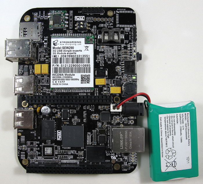
Please refer to image provided below for battery connections

