INDU-RS
Contents
[hide]Overview
Yantrr INDU-RS series of capes provide the capability of interfacing with sensors and instruments using RS232/422/485. These capes are designed to industrial grade I/O interface standards assuring reliable operation and protection in extreme operating environments. The electronics on the capes has been tested to be in compliance with strict EU standards for radiated and conducted emissions.
Utilizing Modbus protocol, these capes can be used to transform VIBE/VIBE2 IoT platform into powerful SCADA & process control systems. INDU-RS capes are also fully compatible with BeagleBone CPU platform.
Quick Start Guide
Following sections gives details of board connectors, pin configuration and various jumpers on INDU-RS3HD, INDU-RS3HD-DC15W boards.
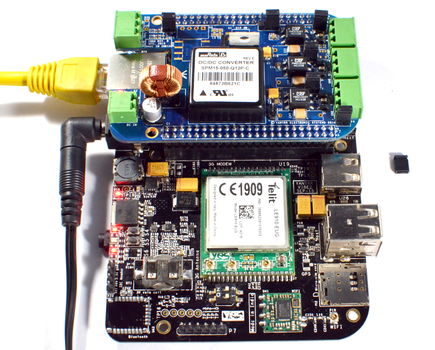
Board Connectors Layout
| INDU-RS3HD | INDU-RS3HD-DC15W |
 |
 |
Pin Connections
Note: INDU-RS485 Headers P6 & P7 correspond to Beaglebone Black [BB] Header P8 & P9 respectively.

Jumper Details
 |

|
| All Jumpers | Jumper P8 |
 |
| Table : Jumpers Details |
Getting Started
Setting up the system
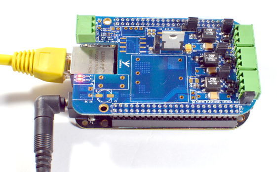
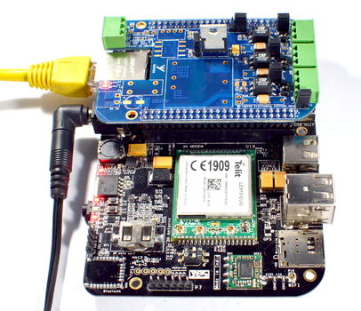
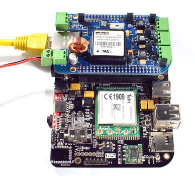
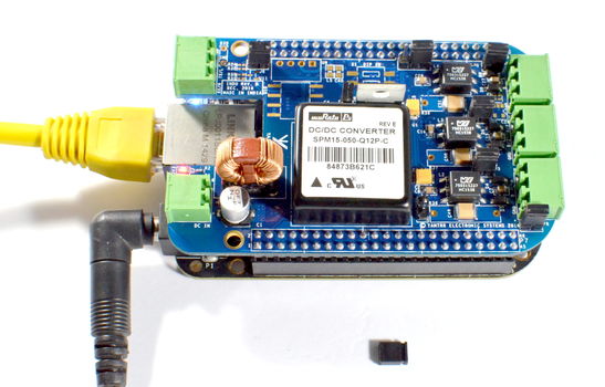
- Mount the INDU-RS cape on Beaglebone Black or Yantrr's VIBE/VIBE2 platform carefully.
- Ensure all the jumpers are in place according to your application use.
- Now power up the full setup
- Note: Before powering up ensure correct software image is loaded in Beaglebone black or VIBE/VIBEQ/VIBE2
- For INDU-RS3HD
- Power up the full setup using a 5V DC adapter(min 2.5A) to barrel jack of Beaglebone Black or VIBE/VIBEQ/VIBE2.
-

Do not try to power up using USB cable alone.
Using Beaglebone Black Using VIBE/VIBEQ/VIBE2 - For INDU-RS3HD-DC15W
-
- You have two option for supplying power:
- 9V-36V DC power through terminal headers supplied to INDU-RS cape
- You have two option for supplying power:

Using Beaglebone Black Using VIBE/VIBEQ/VIBE2 - 5V DC power through normal adapter supplied to Beaglebone Black or VIBE/VIBEQ/VIBE2
Note : For this option, before powering up remove the jumper J1
- 5V DC power through normal adapter supplied to Beaglebone Black or VIBE/VIBEQ/VIBE2
Using Beaglebone Black Using VIBE/VIBEQ/VIBE2 Software Setup Guide
In general the RE/DE input requires high level while transmitting data and low level while receiving data, whereas the standard RTS signal of UART remain low while transmitting data and high while receiving a data.With INDU-RS3HD and INDU-RS3HD-DC15W capes, respective UART of RS485-Port can be put in RS485 mode which will automatically handles RE/DE signal using its RTS pin.
For use of INDU-RS3HD and INDU-RS3HD-DC15W, basic software setup is required for loading correct 8250 driver and assigning correct RTS pins to UART ports at the runtime using Device Tree Overlays.
Software Images
The INDU-RS series capes are tested with latest-release image from beagleboard.org which has inbuilt support for OMAP internal UART (8250 based driver).
Currently INDU-RS485 cape is tested with beaglebone black kernel version 4.9.
Precompiled Images
- Debian
- MicroSD card Image :
- INDU-4.9-debian-9.3-2gb.img.xz (Beaglebone Black)
- MicroSD card Image :
For Beaglebone Black, We recommend to use pre-compiled Debian Yantrr Image. The pre-compiled Debian Yantrr Image comes with all the necessary support for OMAP internal UART (8250 based driver) and all the settings pre-configured for all port of the cape.

Following instructions are only for Users compiling Beaglebone Black's Debian Image from scratch for INDU use.
Configuration for UART1
In order to use UART1 port of this cape, it is required to reconfigure the BeagleBone header’s I2C2_SCL pin as UART1 RTS control.

These steps are needed only if you want to use UART1 at the expense of I2C2 disabled.
I2C2 pins are enabled by default and take precedence over any overlay. So, for the use of UART1 in RS485 mode, the I2C2 pinmux should be disabled.
Steps : (To be executed on Beaglebone-Black/VIBE/VIBE2)
- Clone the repo :
cd /root/
git clone https://github.com/RobertCNelson/dtb-rebuilder.git
cd dtb-rebuilder
git checkout 7e5035a88eab760538481f52d262429c37b6e757
- Verify the dtc version should be latest one
dtc --version
Version: DTC 1.4.4
- Upgrade the dtc
./dtc-overlay.sh
- Disable I2C2 pinmux
cd /root/dtb-rebuilder
Open am335x-bone-common.dtsi and search for &i2c2 section. This is the section concerning i2c2.
nano src/arm/am335x-bone-common.dtsi
Comment out line pinctrl-0 = <&i2c2_pins> under &i2c2, like shown below
&i2c2 {
        pinctrl-names = "default";
        //pinctrl-0 = <&i2c2_pins>;

       status = "okay";
       clock-frequency = <100000>;

       cape_eeprom0: cape_eeprom0@54 {
               compatible = "at,24c256";
               reg = <0x54>;
               #address-cells = <1>;
               #size-cells = <1>;
               cape0_data: cape_data@0 {
                       reg = <0 0x100>;
               };
       };
- Rebuild dtb
make clean
make
make install
- Reboot Beaglebone-Black/VIBE/VIBE2 for applying changes
reboot
Configuration for UART4 and UART5
For use of UART4 and UART5 the HDMI should be disabled.
- Disable HDMI
Uncomment the line dtb=am335x-boneblack-emmc-overlay.dtb in /boot/uEnv.txt file.
nano /boot/uEnv.txt
#Docs: http://elinux.org/Beagleboard:U-boot_partitioning_layout_2.0

uname_r=4.4.34-ti-r69

##BeagleBone Black/Green dtb's for v4.1.x (BeagleBone White just works..)

##BeagleBone Black: HDMI (Audio/Video) disabled:
dtb=am335x-boneblack-emmc-overlay.dtb

##BeagleBone Black: eMMC disabled:
#dtb=am335x-boneblack-hdmi-overlay.dtb

##BeagleBone Black: HDMI Audio/eMMC disabled:
#dtb=am335x-boneblack-nhdmi-overlay.dtb

##BeagleBone Black: HDMI (Audio/Video)/eMMC disabled:
#dtb=am335x-boneblack-overlay.dtb

##BeagleBone Black: wl1835
#dtb=am335x-boneblack-wl1835mod.dtb

##BeagleBone Green: eMMC disabled
#dtb=am335x-bonegreen-overlay.dtb

cmdline=coherent_pool=1M quiet cape_universal=enable

#In the event of edid real failures, uncomment this next line:
#cmdline=coherent_pool=1M quiet cape_universal=enable video=HDMI-A-1:1024x768@60e

##Example v3.8.x
#cape_disable=capemgr.disable_partno=
#cape_enable=capemgr.enable_partno=

##Example v4.1.x
#cape_disable=bone_capemgr.disable_partno=
#cape_enable=bone_capemgr.enable_partno=

##enable Generic eMMC Flasher:
##make sure, these tools are installed: dosfstools rsync
##cmdline=init=/opt/scripts/tools/eMMC/init-eMMC-flasher-v3.sh
In latest Beaglebone Black Debian images the device tree overlays are enabled using U-Boot Overlays approach by default. In previous old images these were enabled using Kernel Overlays approach. The Beaglebone community is still in transition for supporting various applications using U-Boot overlays approach. So, currently our device supporting and tested with kernel overlays approach.
- Reboot Beaglebone-Black/VIBE/VIBE2 for applying changes
reboot
Device Tree Overlays
For particular RS485 port two dtbo files are there
- BB-UART*-00A0.dtbo
- BB-UART*-RTSCTS-00A0.dtbo
Note : * represents the particular port no. of UART used in respective RS485 port. For example, for RS485-Port1 it will be UART4.
The BB-UART*-00A0.dtbo file defines the TX and RX pin configuration of particular UART port. While BB-UART*-RTSCTS-00A0.dtbo file defines the RTS and CTS pin configuration of UART port.
For sending data from any RS485 port, both dtbo files(BB-UART & BB-UART-RTSCTS) of associated UART port should be exported to slots before actual sending of data.
For reading data from any RS485 port, only BB-UART dtbo file is sufficient to get data from associated UART port.
The device tree overlays are compiled as per instructions listed in link https://github.com/RobertCNelson/bb.org-overlays.
Steps
- Clone the repo
cd /root/
git clone https://github.com/beagleboard/bb.org-overlays.git
cd ./bb.org-overlays
- Verify the dtc version should be latest one
dtc --version
Version: DTC 1.4.1-gXYZXYZXYZ
- Upgrade the dtc
./dtc-overlay.sh
- Copy INDU-RS485 related dts files after extracting INDU-RS-Test.tar.gz file in root directory
wget -c http://wiki.yantrr.com/images/1/15/INDU-RS-Test.tar.gz
tar xf INDU-RS-Test.tar.gz
cd INDU-RS-Test/Device_Tree/dts/
cp * /root/bb.org-overlays/src/arm/
- Install *.dtbo
cd /root/bb.org-overlays
./install.sh
Note: This will copies all the dtbo files after compilation automatically in directory /lib/firmware/
- capemgr: enable/disable capes on kernel cmdline:
Comma delimited list of PART-NUMBER[:REV] of [enabled/disabled] capes
bone_capemgr.enable_partno=
bone_capemgr.disable_partno= - capemgr: enable/disable capes with slots:
root@beaglebone:~# cat /sys/devices/platform/bone_capemgr/slots
 0: PF----  -1
 1: PF----  -1
 2: PF----  -1
 3: PF----  -1
- Add Device :
root@beaglebone:~# sh -c "echo 'BB-UART4' > /sys/devices/platform/bone_capemgr/slots"
root@beaglebone:~# cat /sys/devices/platform/bone_capemgr/slots
 0: PF----  -1
 1: PF----  -1
 2: PF----  -1
 3: PF----  -1
 4: P-O-L-   0 Override Board Name,00A0,Override Manuf,BB-UART4
- Remove Device:
root@beaglebone:~# sh -c "echo '-4' > /sys/devices/platform/bone_capemgr/slots"
root@beaglebone:~# cat /sys/devices/platform/bone_capemgr/slots
 0: PF----  -1
 1: PF----  -1
 2: PF----  -1
 3: PF----  -1
RS-485 Ports Testing
Initial Setup
- Export dtbo files of UART1,UART4 and UART5 to slots
sh -c "echo 'BB-UART1' > /sys/devices/platform/bone_capemgr/slots"
sh -c "echo 'BB-UART1-RTSCTS' > /sys/devices/platform/bone_capemgr/slots"
sh -c "echo 'BB-UART4' > /sys/devices/platform/bone_capemgr/slots"
sh -c "echo 'BB-UART4-RTSCTS' > /sys/devices/platform/bone_capemgr/slots"
sh -c "echo 'BB-UART5' > /sys/devices/platform/bone_capemgr/slots"
sh -c "echo 'BB-UART5-RTSCTS' > /sys/devices/platform/bone_capemgr/slots"
- Check slots
root@beaglebone:~# cat /sys/devices/platform/bone_capemgr/slots
 0: PF----  -1
 1: PF----  -1
 2: PF----  -1
 3: PF----  -1
 4: P-O-L-   0 Override Board Name,00A0,Override Manuf,BB-UART1
 5: P-O-L-   1 Override Board Name,00A0,Override Manuf,BB-UART1-RTSCTS
 6: P-O-L-   0 Override Board Name,00A0,Override Manuf,BB-UART4
 7: P-O-L-   1 Override Board Name,00A0,Override Manuf,BB-UART4-RTSCTS
 8: P-O-L-   0 Override Board Name,00A0,Override Manuf,BB-UART5
 9: P-O-L-   1 Override Board Name,00A0,Override Manuf,BB-UART5-RTSCTS
Execution
Test Code : INDU-RS-Test.tar.gz
- Compile the code
cd /root/INDU-RS-Test/src/
gcc -o read-write read-write.c
- Connect A and B lines of RS485-PORT1 to RS485-Port2 and RS485-Port3.
- Note : All connection are limited to single INDU-RS cape
- Start execution
cd /root/INDU-RS-Test/src/
./auto.sh read-write 1
Note : Here the read-write is executable file name which is used while compilation and 1 is loop count, you can increase it to run the test for multiple times.
Result
Now after performing the execution as explained above, the final result will be printed at last on terminal
root@Yantrr:~/INDU-RS-Test/src# ./auto.sh read-write 2
Setting all ports
Port is : /dev/ttyS1
Port is : /dev/ttyS5
Port is : /dev/ttyS4
/dev/ttyS1 : RS485 Mode Enabled
/dev/ttyS4 : RS485 Mode Enabled
/dev/ttyS5 : RS485 Mode Enabled
////////////////////////////////////////////////////////
LOOP COUNT=1
////////////////////////////////////////////////////////

Message sent on port /dev/ttyS1=MESSAGE_ABCDEFGHIJKLMNOPQRSTUVWXYZ_MESSAGE


Message received on port /dev/ttyS4: MESSAGE_ABCDEFGHIJKLMNOPQRSTUVWXYZ_MESSAGE
Message received on port /dev/ttyS5: MESSAGE_ABCDEFGHIJKLMNOPQRSTUVWXYZ_MESSAGE

Message sent on port /dev/ttyS4=MESSAGE_ABCDEFGHIJKLMNOPQRSTUVWXYZ_MESSAGE


Message received on port /dev/ttyS1: MESSAGE_ABCDEFGHIJKLMNOPQRSTUVWXYZ_MESSAGE
Message received on port /dev/ttyS5: MESSAGE_ABCDEFGHIJKLMNOPQRSTUVWXYZ_MESSAGE

Message sent on port /dev/ttyS5=MESSAGE_ABCDEFGHIJKLMNOPQRSTUVWXYZ_MESSAGE


Message received on port /dev/ttyS1: MESSAGE_ABCDEFGHIJKLMNOPQRSTUVWXYZ_MESSAGE
Message received on port /dev/ttyS4: MESSAGE_ABCDEFGHIJKLMNOPQRSTUVWXYZ_MESSAGE
////////////////////////////////////////////////////////
LOOP COUNT=2
////////////////////////////////////////////////////////

Message sent on port /dev/ttyS1=MESSAGE_ABCDEFGHIJKLMNOPQRSTUVWXYZ_MESSAGE


Message received on port /dev/ttyS4: MESSAGE_ABCDEFGHIJKLMNOPQRSTUVWXYZ_MESSAGE
Message received on port /dev/ttyS5: MESSAGE_ABCDEFGHIJKLMNOPQRSTUVWXYZ_MESSAGE

Message sent on port /dev/ttyS4=MESSAGE_ABCDEFGHIJKLMNOPQRSTUVWXYZ_MESSAGE


Message received on port /dev/ttyS5: MESSAGE_ABCDEFGHIJKLMNOPQRSTUVWXYZ_MESSAGE
Message received on port /dev/ttyS1: MESSAGE_ABCDEFGHIJKLMNOPQRSTUVWXYZ_MESSAGE

Message sent on port /dev/ttyS5=MESSAGE_ABCDEFGHIJKLMNOPQRSTUVWXYZ_MESSAGE


Message received on port /dev/ttyS1: MESSAGE_ABCDEFGHIJKLMNOPQRSTUVWXYZ_MESSAGE
Message received on port /dev/ttyS4: MESSAGE_ABCDEFGHIJKLMNOPQRSTUVWXYZ_MESSAGE
////////////////////////////////////////////////////////
RESULTS OF DATA TRANSFER
////////////////////////////////////////////////////////

Total data sent on /dev/ttyS1= 2

Total data received on /dev/ttyS1= 4

Correct data received on /dev/ttyS1= 4

Total data sent on /dev/ttyS4= 2

Total data received on /dev/ttyS4= 4

Correct data received on /dev/ttyS4= 4

Total data sent on /dev/ttyS5= 2

Total data received on /dev/ttyS5= 4

Correct data received on /dev/ttyS5= 4
////////////////////////////////////////////////////////
Exiting
root@Yantrr:~/INDU-RS-Test/src#
CAN Testing
Initial Setup
INDU-CAN cape uses Beaglebone Black's native DCAN1 pins i.e. P9_24 and P9_26, so no need of additional device tree overlays to support on Beaglebone Black/VIBE/VIBEQ/VIBE2.
CAN Utility Setup
- Install the build-tools
apt-get update
apt-get install build-essential git-core automake libtool
- Install SocketCAN utilities
git clone https://github.com/linux-can/can-utils.git
cd can-utils
./autogen.sh
./configure
make
make install
- Configure CAN Interface
To start the CAN interface at system startup edit /etc/network/interfaces file
nano /etc/network/interfaces
Add following lines in it
# CAN Interface
allow-hotplug can0
 iface can0 can static
    bitrate 115200
Enable CAN Bus
- Export dtbo file BB-CAN1
sh -c "echo 'BB-CAN1' > /sys/devices/platform/bone_capemgr/slots"
- Check slots
root@beaglebone:~# cat /sys/devices/platform/bone_capemgr/slots
 0: PF----  -1
 1: PF----  -1
 2: PF----  -1
 3: PF----  -1
 4: P-O-L-   0 Override Board Name,00A0,Override Manuf,BB-UART4
 5: P-O-L-   1 Override Board Name,00A0,Override Manuf,BB-UART4-RTSCTS
 6: P-O-L-   2 Override Board Name,00A0,Override Manuf,BB-UART5
 7: P-O-L-   3 Override Board Name,00A0,Override Manuf,BB-UART5-RTSCTS
 8: P-O-L-   4 Override Board Name,00A0,Override Manuf,BB-UART2
 9: P-O-L-   5 Override Board Name,00A0,Override Manuf,BB-CAN1
On Beaglebone Black/VIBE/VIBEQ/VIBE2 the native DCAN1 pins i.e. P9_24 and P9_26 are pinmuxed with UART1's TXD and RXD respectively, so make sure UART1 is disabled for use of CAN.
- Load the kernel-drivers for the CAN-Bus
sudo modprobe can
sudo modprobe can-dev
sudo modprobe can-raw
- Bring-Up and Configure the CAN Interface
ip link set can0 up type can bitrate 115200
ifconfig can0 up
If gets any issue such as Device or resource busy, run following commands
ifdown can0
ip link set can0 up type can bitrate 115200
Usage
- Send CAN Message
For sending CAN message use command cansend.
For example,for sending a CAN-message to the address 0x5a1 with the databyte[0..5]=0,1,2,3,4 use command
root@beaglebone:~# cansend can0 5A1#00.01.02.03.05
- Receive CAN Message
To log/receive the messages on the CAN Bus from other end, use command candump
root@beaglebone:~# candump can0
 can0  5A1   [5]  00 01 02 03 04
- Note: Before powering up ensure correct software image is loaded in Beaglebone black or VIBE/VIBEQ/VIBE2


