Difference between revisions of "INDU-RS"
(→Jumper Details) |
(→Setting up the system) |
||
| Line 75: | Line 75: | ||
|style=" background:white; color:black" width="100"|'''Using VIBE/VIBE2''' | |style=" background:white; color:black" width="100"|'''Using VIBE/VIBE2''' | ||
|} | |} | ||
| − | |||
::; For INDU-RS3HD-DC15W : | ::; For INDU-RS3HD-DC15W : | ||
::::You have two option for supplying power: | ::::You have two option for supplying power: | ||
| − | |||
::::* 9V-24V DC power through terminal headers supplied to INDU-RS cape | ::::* 9V-24V DC power through terminal headers supplied to INDU-RS cape | ||
| + | {|style="background:white; border:0px solid dimgray;color:white" border="0" height="230" align="center" valign="bottom" cellpadding=20px cellspacing=5px width="auto" | ||
| + | |||
| + | <!--Start of the details for the top-of-table heading--> | ||
| + | <!--|+style="background:white; color:black"|'''''INDU-RS3HD'''--''> | ||
| + | |||
| + | <!--Start the first row and add row formats--> | ||
| + | |-align="center" | ||
| + | <!--Start of individual cell details for the first row--> | ||
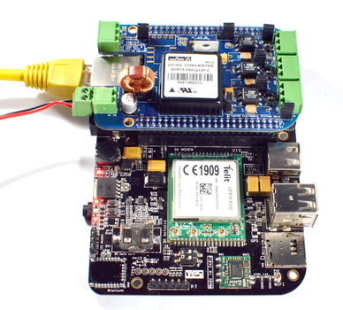
| + | |[[Image:INDU-RS_BBB_2.jpg|border|800x350px|none]] | ||
| + | |[[Image:INDU-RS_VIBE2_2.jpg|border|800x350px|none]] | ||
| + | |||
| + | <!--Start of a second row and add formats--> | ||
| + | |-align="center" valign="top" | ||
| + | <!--Start of individual cell details for the second row--> | ||
| + | |style=" background:white; color:black" width="100"|'''Using Beaglebone Black''' | ||
| + | |style=" background:white; color:black" width="100"|'''Using VIBE/VIBE2''' | ||
| + | |} | ||
| + | |||
| + | ::::* 5V DC power through normal adapter supplied to Beaglebone Black or VIBE/VIBE2<br />''Note : For this option, before powering up remove the jumper J1'' | ||
=Software Setup Guide= | =Software Setup Guide= | ||
* INDU-RS3HD, INDU-RS3HD-DC15W | * INDU-RS3HD, INDU-RS3HD-DC15W | ||
Revision as of 02:49, 14 March 2017
Contents
[hide]Overview
Yantrr INDU-RS series of capes provide the capability of interfacing with sensors and instruments using RS232/422/485. These capes are designed to industrial grade I/O interface standards assuring reliable operation and protection in extreme operating environments. The electronics on the capes has been tested to be in compliance with strict EU standards for radiated and conducted emissions.
Utilizing Modbus protocol, these capes can be used to transform VIBE/VIBE2 IoT platform into powerful SCADA & process control systems. INDU-RS capes are also fully compatible with BeagleBone CPU platform.
Quick Start Guide
Following sections gives details of board connectors, pin configuration and various jumpers on INDU-RS3HD, INDU-RS3HD-DC15W boards.
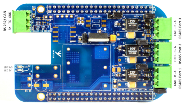
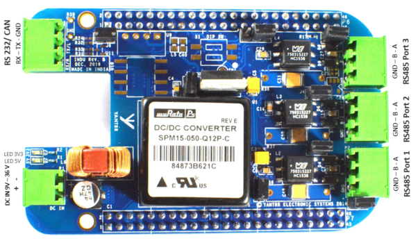
Board Connectors Layout
| INDU-RS3HD | INDU-RS3HD-DC15W |
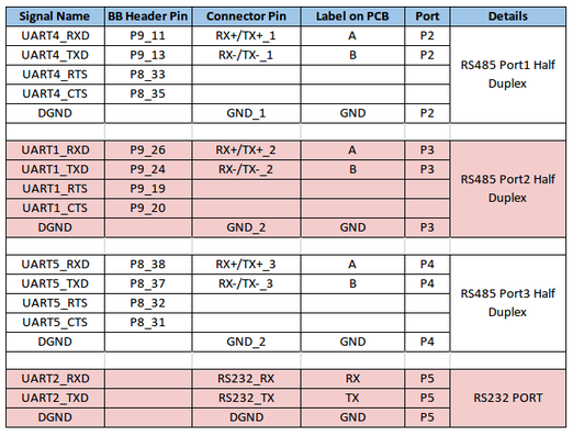
Pin Connections
Note: INDU-RS485 Headers P6 & P7 correspond to Beaglebone Black [BB] Header P8 & P9 respectively.
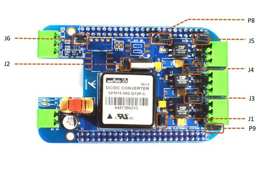
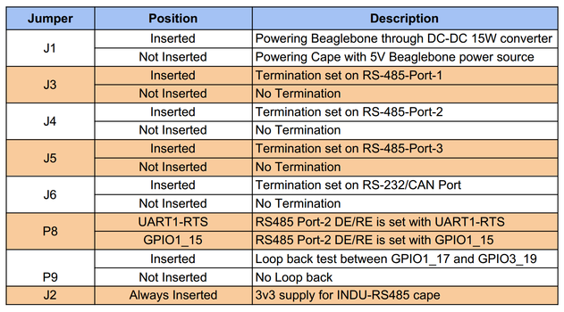
Jumper Details
Getting Started
Setting up the system
- Mount the INDU-RS cape on Beaglebone Black or Yantrr's VIBE/VIBE2 platform carefully.
- Ensure all the jumpers are in place according to your application use.
- Now power up the full setup
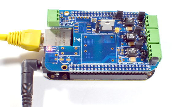
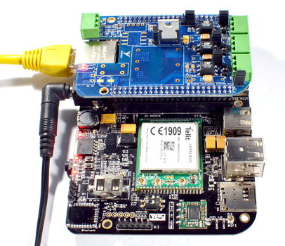
- For INDU-RS3HD
- You have to supply 5V DC power supply to Beaglebone Black or VIBE/VIBE2.
| Using Beaglebone Black | Using VIBE/VIBE2 |
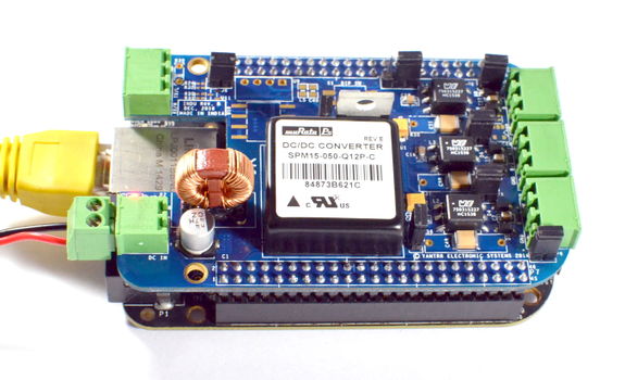
- For INDU-RS3HD-DC15W
-
- You have two option for supplying power:
- 9V-24V DC power through terminal headers supplied to INDU-RS cape
- You have two option for supplying power:
| Using Beaglebone Black | Using VIBE/VIBE2 |
- 5V DC power through normal adapter supplied to Beaglebone Black or VIBE/VIBE2
Note : For this option, before powering up remove the jumper J1
- 5V DC power through normal adapter supplied to Beaglebone Black or VIBE/VIBE2
Software Setup Guide
- INDU-RS3HD, INDU-RS3HD-DC15W
